- +91 9823101312
- +91 9967248672
- sales@rmbknovatech.com
Vibrating Pan Feeder
Vibrating Pan Feeder
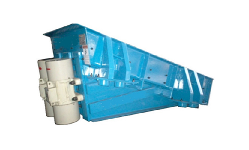
KVF series vibrating Pan Feeder
Type: Extraction from hopper, bin and Control Feeding equipment
Feed Size: Greater than 0 and up to 500mm
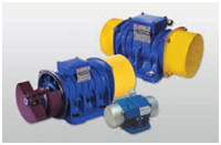
Mode of Vibration: Linear Motion with Electromechanical unbalance Motor
Capacity: 50-600 TPH
Materials: Aggregate (River stone, gravel, granite, basalt, mineral, quartz, diabase), Iron ore, copper ore, cement, artificial sand, fluorite, limestone, slag ,food and chemicals etc
Applications: Mining, metallurgy,Cement,Thermal Power,Chemical and pharmaceuticals, Engineering and material, Sugar food processing , glass industries, construction, highway, railroad, water conservancy, etc.
Overview
KVF series vibrating feeder uses vibrating motor to produce vibration force. unbalance drives are economical conveying means for all bulk material and are used where products are to be fed either Continuously or batch for instance -
- Discharging bulk materials form bins.
- Feeding crushers, mixers, furnaces & scales.
- Feeding conveyor belts, bucket elevators.
- Vibratory screens, loading & sorting plants.
Compare to other conveying means vibrating feeders with unbalance motors have low energy consumption. Trough is provided with wear resistant liners and they do not influence the quality and character of the product they handle. Unbalance Motors provided with the feeder are robust, reliable in operation have a high loading capacity and with least maintenance. They have generously dimensioned special heavy vibration proof winding, totally enclosed with IP-55 degree of protection and are suitable for weather proof outdoor.
Features and technology advantages
RMB Knovatech Vibrating Pan Feeder reduces maintenance cost and lower capital expenditure
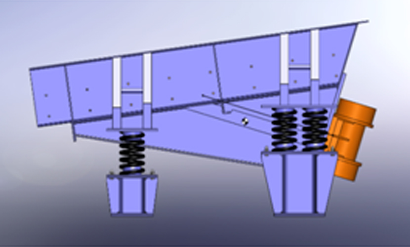
- Vibrating Body
- Conveying Trough with wear liner
- Electro-mechanical Vibrating Motor
- Coil Spring Units for better isolation
- Heavy duty Structures
- Feeding Mouth
- Regulate feed rate to the plant
Working principle of Pan Feeder
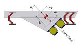
The oscillating motion of the Feeder is imparted by the unbalance masses mounted on the extended shaft of the two Motor rotating at the same speed but in opposite direction. These motors are placed symmetrically about a line at right angle to the frame. As the resultant force due to unbalance masses passes through this line, it is called drive line. The total displacement in either direction is called “stroke” As it may be observed that at any instant of 360 rotation of the motors, individual motors are producing forces with components along the drive line and also at right angle to it. The forces at right angle to the drive line produced, are at opposite directions and cancel each other, leaving the forces only in the direction of the drive line.
Technical Data :
| Model | Width x Length (mm) | Capacity (tph)* | Unbalance Motor Kw x rpm x qty | Vibrating Type | Acceleration (g force) | App. Wt.(kg) | |
|---|---|---|---|---|---|---|---|
| Vibrating | Static | ||||||
| KVF 80/150-B | 800 x 1500 | 100-150 | 0.75 KW x1500 RPMX2 Nos. | Linear | 3.0<G<5.0 | 750 | 350 |
| KVF 100/180-B | 1000 x 1800 | 150-200 | 1.1 KW x1500 RPMX2 Nos. | Linear | 3.0<G<5.0 | 1050 | 450 |
| KVF 120/200-B | 1200 x 2000 | 200-300 | 1.5 KW x1500 RPMX2 Nos. | Linear | 3.0<G<5.0 | 1250 | 550 |
| KVF 140/240-B | 1400 x 2400 | 300-400 | 2.1 KW x1500 RPMX2 Nos. | Linear | 3.0<G<5.0 | 1450 | 750 |
Note : The capacity per hour is consider onthe basis of bulk density with 1.6x10³kg/m³.Capacities are relative to physical character and type of feeding, feeding size and composition and so on
Download Brochure