- +91 9823101312
- +91 9967248672
- sales@rmbknovatech.com
Rotary Air Lock
Rotary Air Lock
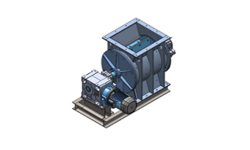

Rotary Air Lock
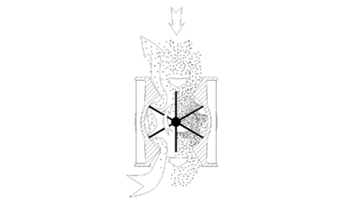
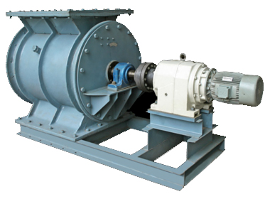
The prime function of a rotary valve is to regulate the flow from one chamber to another while maintaining a good airlock condition. The product is mainly in dry powder or granular form. In the dust filtration field good airlocks are essential on cyclone and bag filter applications in order that the manufacturer’s quoted high dust collection efficiencies can be maintained. Airlocks are also important in the pneumatic conveying industry, where product is regulated into a high-pressure conveying line while minimising air leakage. All RMB Knovatech standard valves are precision machined for close tolerances and minimal eccentricities. Pressure differentials up to 15 bar and temperatures up to 400°C.
Standard Feature
- Maximum number of blades in contact with body at one time without affecting throughput. Good throat opening at valve entry allowing high pocket filling efficiency.
- Minimum clearance at rotor tips and sides with body.
- Robust body adequately stiffened to prevent distortion.
- Heavy shaft diameters minimising deflection.
- Outboard bearings for non-contamination.
- Labyrinth/Packing gland type seals.
- Maximizing valve speed to 25 rpm -prolonging life, ensuring good throughput.
- Precision machining of components
Construction / Technical Specification
| Body | Fabricated-MS/SS |
|---|---|
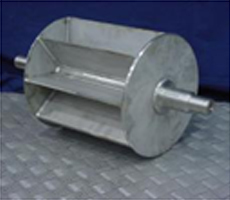
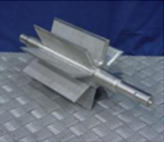
| Rotor | Fabricated Closed and Open, MS/SS |
| Side Plates | Fabricated MS/SS |
| Gear Box | Heliworm / Helibevel / Helical Gear |
| Drive Type | Direct/Chain |
| Drive | Bonfiglioli Standard |
| Rotor Type | Fabricated Closed or open |
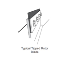
| Rotor Tips | Flexible Tips/Wear Tips |
| Sensor | Proximity Sensor |
| Seals | Labyrinth Seal |
| Bearing | Cartridge Type |
|---|---|
| Bearing Make | SKF/NTN/ZKL eqvt. |
| Shaft | CS1030 |
| Opening Size | 200 to 750 |
| Temperature | UP to 400 Degree C |
| Differential Pressure | 15 Bar |
| Capacity Range | Up to 350 Cu M |
| Surface Treatment | Grit Blasting |
| Painting Standard | 50 µm Epoxy Grey Primer and 50 µm PU Blue paint RAL 5015 |
Selection
The chart below gives theoretical and estimated throughputs on the basis of rotor speed. The theoretical figure is determined by the swept volume of the valve and is calculated on a pocket fillage of 100%. In practice this is seldom achieved as density, product characteristics, pressure differential, feeding methods, all affect the valve throughput efficiency. Factors other than throughput can sometimes determine valve selection. This is particularly true on cyclone and filter applications where the valve inlet size to prevent bridging can become the governing factor,always with the proviso that the potential valve discharge rate exceeds the collecting rate.
| Model | Opening (MM) | Power | Capacity Chart In CU M PER HR considering 100%filling | |||||
|---|---|---|---|---|---|---|---|---|
| RPM | 26 | 24 | 22 | 20 | 18 | 16 | ||
| KH750 | 750x750 | 7.5 | - | - | - | 420 | 360 | 300 |
| KH750 | 750x750 | 7.5 | - | - | - | 420 | 360 | 300 |
| KH600 | 600x600 | 5.5 | - | - | - | 280 | 240 | 200 |
| KH500 | 500x500 | 4 | - | - | 120 | 105 | 90 | 75 |
| KH400 | 400x400 | 3.0 | - | - | 80 | 70 | 60 | 50 |
| KH300 | 300x300 | 1.5 | 50 | 45 | 40 | 35 | 30 | 25 |
| KH200 | 200x200 | 0.75 | 20 | 18 | 16 | 14 | 12 | 10 |
Dimension Direct Drive
| Name | KH200 | KH300 | KH400 | KH500 | KH600 | KH750 |
|---|---|---|---|---|---|---|
| A | 300 | 430 | 530 | 630 | 760 | 930 |
| B | 200 | 300 | 400 | 500 | 600 | 750 |
| C | 517 | 598 | 894 | 1028 | 1068 | 1309 |
| D | 367 | 383 | 629 | 711 | 940 | 1050 |
| E | 150 | 215 | 265 | 315 | 380 | 465 |
| F | 85 | 94 | 94 | 114 | 100 | 108 |
| G | 255 | 376 | 470 | 570 | 700 | 864 |
| H | 14 | 15 | 15 | 15 | 18 | 18 |
| I | 12 | 16 | 20 | 20 | 28 | 32 |
| J | 574 | 718 | 932 | 1089 | 1182 | 1376 |
| K | 190 | 250 | 325 | 375 | 457 | 465 |
| L | 384 | 468 | 607 | 714 | 725 | 911 |
| M | 330 | 470 | 620 | 760 | 900 | 1120 |
| N | 165 | 235 | 310 | 380 | 450 | 560 |
| O | 165 | 235 | 310 | 380 | 450 | 560 |
| Net Weight | 84 | 183 | 400 | 615 | 1058 | 1750 |
| Gross Weight | 105 | 215 | 440 | 750 | 1120 | 1820 |